Category Archives: Industry

Industry

can a undesirable push shaft have an effect on transmission?

Indeed, a undesirable or defective push shaft can certainly affect the transmission of a car or truck. The push shaft is a important ingredient that transfers torque from the transmission to the wheels, permitting the motor vehicle to go. If the push shaft is destroyed, worn out, or improperly balanced, it can lead to quite a few problems that can impression the transmission method. Below are a couple means a poor push shaft can impact the transmission:

one. Vibration and Shuddering: A damaged or unbalanced generate shaft can result in excessive vibrations and shuddering during the automobile. These vibrations can be transmitted to the transmission technique, potentially major to premature don and destruction to transmission elements.

2. Misalignment: A bent or misaligned generate shaft can lead to misalignment amongst the transmission output shaft and the differential enter shaft. This misalignment can result in inappropriate engagement and enhanced friction within just the transmission, primary to issues like equipment slippage, problem in shifting gears, and transmission overheating.

three. Excessive Load on Transmission: A faulty travel shaft may possibly not distribute torque evenly to the wheels, resulting in uneven energy transmission. This imbalance can put extra tension on the transmission, creating it to do the job more challenging and likely top to premature don and failure of transmission parts.

4. Loss of Ability: China drive shaft distributor A broken or disconnected China drive shaft distributor shaft can consequence in a finish loss of power transmission from the transmission to the wheels. This reduction of ability can stop the auto from transferring or severely restrict its capacity to speed up.

It is crucial to deal with any difficulties with the generate shaft instantly to avert injury to the transmission and guarantee harmless and economical operation of the automobile. Regular routine maintenance, together with inspections and correct lubrication of the generate shaft, can help determine and prevent probable problems in advance of they escalate and have an impact on the transmission process.

What are the 3 key pieces of an injection molding equipment?

An injection molding machine usually consists of a few principal areas or components:

1. Injection Device: The injection device is dependable for melting and injecting the plastic product into the mildew. It is made up of various sub-parts:

a. Hopper: The hopper is a container that holds the plastic content in the type of pellets or granules. The content is gravity-fed from the hopper into the injection unit.

b. Barrel and Screw: The barrel is a heated cylindrical chamber exactly where the plastic pellets are melted. Inside of the barrel, there is a reciprocating screw that rotates and moves ahead, pushing the molten plastic materials towards the mould.

c. Nozzle: At the finish of the barrel, there is a nozzle that connects to the mold. The molten plastic material passes by the nozzle and into the mold’s runners, gates, and China Injection molded parts cavities.

two. Clamping Device: The clamping device is liable for securely keeping the mold halves jointly all through the injection molding system. It consists of the following elements:

a. Mildew Plates: The mould plates deliver the mounting surface area for the mildew halves. The cavity aspect of the mould is mounted on the stationary platen, while the main aspect is mounted on the shifting platen.

b. Clamping System: The clamping mechanism applies and maintains the required pressure to continue to keep the mold shut throughout injection. It typically is made up of hydraulic or mechanical methods, which includes toggle clamps or hydraulic cylinders, that exert strain to keep the mould halves alongside one another.

c. Movable Platen: The movable platen is connected to the clamping system and moves back and forth to open and close the mould. It is responsible for separating the mould halves through element ejection.

three. Handle Procedure: The manage process of an injection molding machine manages and regulates the full injection molding course of action. It contains a variety of components and interfaces that regulate and check the machine’s operation, these types of as:

a. Handle Panel: China Injection molded parts exporter The management panel delivers a person interface for operators to established and change method parameters, this kind of as temperature, stress, China Injection molded parts supplier speed, and cycle time. It also displays actual-time data and diagnostics.

b. Hydraulic or Electric Management Method: The injection molding device can be geared up with either hydraulic or electric powered management programs to management the machine’s actions and features. These programs assure exact handle of the injection, clamping, and ejection procedures.

c. Sensors: Sensors are built-in into the device to keep an eye on and supply feedback on parameters like temperature, China Injection molded parts supplier force, place, and cycle time. The handle procedure uses this info to sustain optimal system circumstances and be certain consistent section top quality.

The a few major areas of an injection molding equipment get the job done collectively to melt the plastic substance, inject it into the mould, securely maintain the mold closed, and handle the full course of action. Each individual section plays a crucial position in achieving productive and accurate production of injection molded elements.

how to style injection molded elements

Creating injection molded sections needs careful thought of several components to make certain productive molding and performance of the final merchandise. Right here are some ways to guideline you in the style approach:

1. Outline the Specifications: Clearly establish the useful specifications, desired capabilities, and efficiency standards for the injection molded aspect. Take into account variables this kind of as part geometry, materials choice, mechanical houses, dimensional tolerances, floor finish, and any distinct marketplace requirements or rules.

two. Content Collection: Pick a acceptable thermoplastic material for China Injection molded parts manufacturer molding based on your prerequisites. Consider aspects this sort of as mechanical qualities, chemical resistance, temperature resistance, cost, and availability. Consult substance datasheets and collaborate with content suppliers to make an educated conclusion.

3. Aspect Geometry and Draft Angles: Layout the component geometry, which include walls, ribs, bosses, and other functions, with thing to consider for moldability. Integrate draft angles (tapered surfaces) to facilitate simple portion ejection from the mold and avoid undercuts. Satisfactory draft angles generally vary from .five to two degrees, based on the content and component dimension.

four. Wall Thickness: Maintain uniform wall thickness throughout the part to ensure proper movement of molten plastic all through injection molding. Various wall thickness can lead to uneven cooling, warping, or sink marks. Usually, goal for a wall thickness in between 1-5 mm, dependent on the part dimension and product.

5. Gate Placement: Decide suited gate spots for the injection of molten plastic into the mildew cavity. Gate placement impacts the filling pattern, part overall look, and materials circulation. Frequent gate sorts involve edge gates, pin-stage gates, or sub-gates. Prevent positioning gates on critical surfaces or areas requiring a high beauty complete.

6. Ribs and Fillets: Include ribs to maximize part stiffness though reducing content use. Use fillets or rounded corners to lessen tension focus and aid product move throughout molding. Keep correct thickness and top ratios involving ribs and adjacent walls to keep away from sink marks or warpage.

seven. Draft Evaluation and Mildew Movement Simulation: Make the most of design software package or seek the advice of with mold designers to carry out draft examination and mould movement simulations. These equipment enable determine prospective molding concerns, improve gate destinations, review fill patterns, forecast warpage, and improve cooling channels.

8. Ejection and Parting Line: Layout suited characteristics for component ejection, such as ejector pins or ejector sleeves. Establish the parting line, which is the separation line concerning mould halves, and make sure it does not interfere with vital surfaces or functions.

9. Area End and Texture: Specify the sought after surface end and texture for the section. Contemplate cosmetic needs, useful demands (such as grip or slip resistance), China Injection molded parts manufacturer and the capabilities of the decided on mildew and substance.

ten. Design for Producing and Assembly: Consider simplicity of producing and assembly through the layout system. Lower the selection of factors, use snap-fit or interlocking functions in which proper, and make certain correct alignment and match in between mating sections.

11. Prototype and Testing: Produce prototypes or 3D-printed types to assess the design and style, healthy, functionality, and functionality of the injection molded portion. Conduct screening to validate the style and design towards the outlined needs.

It is really crucial to collaborate with seasoned injection mildew designers and manufacturers in the course of the style and design procedure to optimize the section design for thriving injection molding. They can give useful insights, provide design and style suggestions, and enable handle potential manufacturing issues.

What are the advantages of cycloidal gearbox?

Cycloidal gearboxes provide several strengths that make them common in a variety of industrial applications. Right here are some key advantages of cycloidal gearboxes:

Free photo close-up of motorcycle parts1. Large Torque Capacity: Cycloidal gearboxes give significant torque output relative to their sizing. The cycloidal motion theory makes it possible for several points of get hold of in between the input and output parts, distributing the load and enabling substantial torque transmission. This makes cycloidal gearboxes nicely-suited for applications that call for significant torque, these types of as robotics and heavy machinery.

2. Compact Dimensions: Cycloidal gearboxes are recognised for their compact and space-conserving design. They have a high electrical power density, indicating they can deliver a substantial sum of torque in a tiny package. The compact dimension can make them excellent for programs the place area is minimal or the place a compact, light-weight layout is desired, these as in robotics or portable machines.

three. Smooth and Specific Movement Manage: The cycloidal motion of the gear components final results in smooth and exact movement manage. This is especially advantageous in applications that call for exact positioning, these types of as robotic arms or CNC devices. The cycloidal movement will help decrease backlash and supplies much better management more than the motion, ensuing in enhanced accuracy and repeatability.

four. Substantial Performance: Cycloidal gearboxes are intended to supply large efficiency in ability transmission. The several factors of get hold of and rolling action of the gear factors lower friction and limit electricity losses, ensuing in economical electrical power transfer. This can direct to energy savings and lowered operating fees in apps exactly where cycloidal gearboxes are employed.

5. Toughness and Reliability: Cycloidal gearboxes are identified for their sturdy design and toughness. The gear factors are designed to distribute the load evenly, cutting down stress concentrations and improving the gearbox’s longevity. Additionally, the compact and China cycloidal gearbox exporter enclosed style and design assists guard the internal elements from contaminants and exterior components, making certain dependable and long-lasting operation.

six. Load Distribution: Cycloidal gearboxes excel at distributing the load throughout many gear enamel or lobes, which will help to limit use and extend the life of the gearbox. The load distribution functionality enhances the gearbox’s means to take care of shock hundreds, overloads, and variants in working situations.

General, the benefits of China cycloidal gearbox exporter gearboxes, which include substantial torque potential, compact sizing, smooth movement command, superior efficiency, durability, and load distribution abilities, make them a well-known preference in a broad variety of programs wherever trusted and efficient ability transmission is critical.

Why helical gears are silent?

Helical gears are identified for China helical gear motor manufacturer their relatively quiet procedure in comparison to some other kinds of gears. The most important cause for their quieter procedure is the gradual engagement and disengagement of the teeth all through rotation. Here is why helical gears have a tendency to be silent:

one. Angled Teeth: Helical gears have tooth that are reduce at an angle to the gear axis, forming a helix form. This angle causes the enamel to have interaction slowly as they come into speak to, alternatively than earning instantaneous speak to like spur gears. The gradual engagement can help to lower effect forces and limit sounds era.

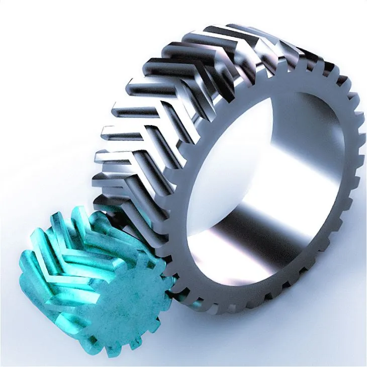
2. Smoother Tooth Make contact with: The angled tooth of China helical gear motor manufacturer gears allow for larger get in touch with regions involving the teeth in comparison to spur gears. This much larger speak to place spreads the load more than multiple tooth, ensuing in a much more even distribution of forces. As a consequence, China helical gear motor manufacturer the teeth working experience diminished localized tension and much less sound-triggering vibration through operation.

3. Load Sharing: The helical tooth profile allows many teeth to be in contact at the same time while transmitting energy. This load-sharing characteristic allows distribute the load throughout a number of teeth, cutting down the tension on person tooth and minimizing sound technology.

four. Lowered Backlash: The helical gear layout inherently minimizes backlash, which is the slight gap between the mating enamel when there is no load utilized. Backlash can direct to sounds and vibration all through gear procedure. The angled teeth of helical gears build a self-aligning outcome that aids reduce backlash, resulting in quieter operation.

five. Lubrication: Good lubrication is critical for the peaceful and smooth operation of helical gears. High-top quality lubricants support lower friction amongst the tooth surfaces, dampen vibrations, and dissipate heat. Adequate lubrication minimizes put on, sound, and raises the over-all performance of the gear program.

Although helical gears give quieter operation compared to some other gear styles, it is crucial to note that other things, such as equipment high-quality, right alignment, and routine maintenance techniques, also lead to the general noise stage of a equipment procedure.

how to connect rack equipment?

To connect a rack equipment, you commonly will need to mount it securely to the wanted area or composition to allow for it to function adequately in a linear motion. This is a general manual on how to link a rack gear:

Equipment Desired:

– Rack equipment

– Mounting brackets or China gear rack exporter supports

– Screws or bolts

– Screwdriver or wrench

– Measuring tape or ruler

– Stage (optional)

Instructions:

one. Identify the mounting site:

– Detect the floor or composition where you want to hook up the rack equipment. This can be a body, wall, or any other stable floor that can assistance the weight and forces involved in the application.

– Make sure that the mounting place is appropriate for the supposed purpose and gives the vital clearance for the rack China gear rack distributor‘s motion.

two. Prepare the rack equipment:

– Measure the size of the rack gear to ascertain the acceptable measurement and placement of mounting brackets or supports.

– If necessary, minimize the rack equipment to the sought after duration working with a observed or other suitable cutting tool. Be thorough to make clean, straight cuts.

three. Mounting brackets or supports:

– Placement the mounting brackets or supports alongside the duration of the rack equipment. The number of brackets will depend on the sizing and weight of the rack equipment, as well as the certain needs of your software.

– Align the brackets or supports evenly alongside the rack gear to make sure balance and appropriate distribution of force.

– Mark the screw or bolt gap places on the surface where the rack equipment will be mounted.

four. Safe the rack equipment:

– Attach the mounting brackets or supports to the floor utilizing screws or bolts. Make sure that the screws or bolts are acceptable for the product of the area and are securely mounted.

– For added steadiness, use a degree to guarantee that the rack equipment is mounted horizontally or as for every your preferred orientation.

five. Take a look at the relationship:

– Carefully slide the rack gear again and forth to exam the smoothness of its motion and make sure that it is securely connected.

– Verify that the rack equipment does not have any too much engage in or wobbling. Make any required adjustments or tighten the mounting screws or bolts if required.

Observe: The precise mounting approach may well differ dependent on the variety of rack equipment and the software. It is critical to refer to the manufacturer’s guidance or seek advice from with an specialist if you have a specialized or complex rack equipment procedure.

Always take into account basic safety safety measures and stick to any more guidelines or tips offered by the company to make certain a safe and trusted connection for your rack gear.

What are the techniques of coupling?

In program engineering, there are a number of procedures or tactics to regulate coupling involving parts or modules. These strategies aim to decrease tight interdependencies and promote free coupling, which enhances modularity, flexibility, and maintainability. Right here are some usually utilised strategies of coupling:

one. Information and China coupling facts Hiding or Encapsulation: Encapsulation is a technique that hides the interior facts and implementation of a component, exposing only needed interfaces or APIs. Parts interact with each and every other by well-defined interfaces, limiting their awareness of just about every other’s interior workings. This decreases coupling factory by decoupling the internal implementation specifics of a component from its shoppers.

two. Abstraction: Abstraction involves representing concepts or entities at a higher degree of generality, China coupling hiding avoidable information. By defining summary interfaces or foundation classes, components can interact based on normal principles alternatively than specific implementations. This enables for free coupling by decreasing dependencies on concrete implementations.

three. Dependency Injection: Dependency injection is a strategy exactly where the dependencies of a ingredient are delivered from external sources instead than becoming established or managed by the component itself. By injecting dependencies as a result of interfaces or configuration, components can be decoupled from particular implementations and conveniently swapped or modified without having influencing other factors.

4. Interface-primarily based Programming: Interface-dependent programming encourages the use of interfaces to outline contracts among components. Components interact with just about every other by means of these interfaces, fairly than specifically dependent on concrete implementations. This encourages unfastened coupling, as factors count on the interface rather than particular implementations.

5. Party-pushed Architecture: Function-pushed architecture involves components communicating with each and every other by situations, where one element triggers an celebration and some others react to it. Components do not instantly rely on each individual other but alternatively subscribe to situations they are fascinated in. This minimizes immediate dependencies and makes it possible for for increased decoupling in between factors.

six. Message Passing: Concept passing consists of conversation involving components by sending messages or knowledge packets. Factors interact by exchanging messages through very well-described channels or protocols. This system decouples factors, as they only have to have to know how to interpret the messages they obtain and do not count on immediate know-how of other elements.

seven. Loose Coupling by means of Layers: Layered architecture consists of organizing factors into layers, the place each layer provides a unique established of functionalities and interfaces. Elements in a increased layer rely on components in reduce layers, but not vice versa. This encourages loose coupling, as higher-degree elements can interact with reduce-amount elements by well-described interfaces, devoid of needing to know the facts of their implementations.

These solutions of coupling administration assist lessen tight interdependencies and market free coupling among factors, major to extra modular, flexible, and maintainable program methods. The alternative of which technique to use is dependent on the unique demands, architecture, and layout concepts of the software system.

how to measure driver shaft duration?

To evaluate the size of a driver shaft, you can stick to these actions:

one. Clear away the driver head: Detach the driver head from the shaft by unscrewing it. This will allow you to properly measure the duration of the shaft.

two. Align the shaft: Lay the shaft on a flat floor, making certain that it is straight and aligned without any bends or curves.

3. Evaluate the size: Starting up from the butt conclusion (grip end) of the shaft, use a measuring tape or a ruler to evaluate the duration of the shaft in inches or centimeters. Spot the measuring tape or ruler along the centerline of the shaft for correct measurement.

4. Evaluate to the conclusion of the tip: Measure all the way to the finish of the tip of the shaft. The idea is the section in which the driver head is usually attached.

five. History the measurement: China drive shaft distributor Once you have calculated the duration of the China drive shaft distributor, record the measurement for long term reference or when getting substitution or custom shafts.

It’s truly worth noting that the duration of the driver shaft is usually calculated devoid of the grip involved. The grip is generally extra independently and can range in length, so it is not ordinarily incorporated in the measurement.

By following these methods, you must be ready to properly evaluate the length of a driver shaft.

how does a cycloidal gearbox work

A cycloidal gearbox, also regarded as a cycloidal travel or cycloidal reducer, is a form of gearbox that takes advantage of a system referred to as the cycloidal movement principle to reach speed reduction and torque multiplication. It is made up of 3 key factors: an input shaft, a established of eccentric pins or cams, and an output shaft.

This is a normal overview of how a cycloidal gearbox will work:

one. Input Shaft: The input shaft is connected to the power source, these kinds of as an electrical motor. It transfers rotational movement and torque to the gearbox.

two. Eccentric Pins or Cams: The input shaft is connected to a established of eccentric pins or cams. These pins or cams are off-center with regard to the enter shaft and are organized in a round pattern all around it.

3. Cycloidal Disc: Bordering the eccentric pins or cams is a cycloidal disc. The disc has lobes or lobed cutouts that correspond to the selection and arrangement of the eccentric pins or cams.

4. Output Shaft: The output shaft is linked to the cycloidal disc. As the eccentric pins or China cycloidal gearbox supplier cams rotate with the input shaft, they result in the China cycloidal gearbox supplier disc to shift in a cycloidal movement.

5. Needle Bearings: The cycloidal disc is supported by needle bearings that make it possible for it to rotate smoothly and retain speak to with the eccentric pins or China cycloidal gearbox distributor cams.

six. Output Rotation: The cycloidal movement of the disc converts the rotational motion from the input shaft into an output rotation. The output shaft is connected to the cycloidal disc and rotates with it. The output velocity and torque are established by the quantity of lobes on the cycloidal disc and China cycloidal gearbox supplier the connection in between the enter and output shafts.

The exclusive feature of a cycloidal gearbox is its ability to realize superior gear reduction ratios with compact dimension and substantial torque output. The cycloidal motion principle allows several factors of make contact with amongst the eccentric pins or cams and the cycloidal disc, distributing the load and rising the gearbox’s torque-carrying capability.

Cycloidal gearboxes are generally made use of in different programs, including robotics, automation, conveyors, and weighty machinery, wherever superior torque, precision, and compactness are necessary.

can a gearbox be repaired

Of course, a gearbox can generally be repaired dependent on the nature and extent of the hurt or malfunction. Gearbox repairs are typically performed by knowledgeable mechanics or specialized gearbox mend retailers. The restore approach can require numerous techniques, together with:

one. Prognosis: The initially phase is to identify the unique difficulty with the gearbox. This could require inspecting the gearbox, conducting assessments, and analyzing any indicators or abnormal noises described by the driver.

2. Disassembly: The gearbox is disassembled to access the inner factors. This could entail taking away the gearbox from the vehicle and getting apart its housing and involved elements.

3. Element Inspection: Each component, including gears, bearings, China gearbox distributor shafts, synchros, and seals, is inspected for put on, China gearbox distributor destruction, or misalignment. Any faulty or worn-out elements are recognized for substitution.

four. Substitute of Defective Sections: Ruined or worn components are changed with new or reconditioned pieces. It can be significant to use high-high quality replacement components to assure the longevity and good functioning of the China gearbox distributor.

five. Reassembly: The gearbox is reassembled with the replaced or fixed parts. This involves proper lubrication, adjustment of clearances, and torque technical specs.

6. Screening and Adjustment: After reassembled, the gearbox is examined to make certain it operates efficiently and with no any issues. Changes might be created to fine-tune the shifting effectiveness and assure correct equipment engagement.

It is value noting that the extent of a gearbox mend can range noticeably dependent on the certain difficulty. In some conditions, slight repairs these types of as changing a seal or bearing may perhaps be adequate. On the other hand, additional elaborate troubles, such as harmed gears or key internal damage, could need a more extensive mend or even a full gearbox replacement.

It truly is encouraged to consult a experienced mechanic or gearbox professional to evaluate the precise difficulty with your gearbox and determine the most appropriate course of action, whether or not it can be a maintenance or substitution.